The previous post discussed how the process works to get some code running on a microcontroller. This post ought to be a bit more productive, as it will discuss how to actually do some stuff with that code. All microcontroller software has something to do with input and output (I/O), so let's first discuss what digital I/O is.
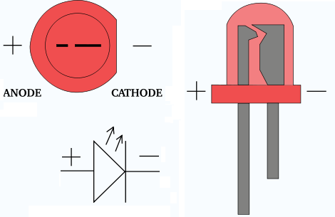
If we trace the circuit, we see that there is a direct connection to the Arduino ground pin, indicating that it must be the current sink. Therefore, we must be using digital pin 13 (D13) as the current source. Another point that enforces this is that LEDs only work in one direction, i.e. one particular leg (the longer one) must have a higher potential than the other. The schematic shows this with the LED symbol, which kinda looks like an arrow. The second important piece to notice is the resistor. Without it, the current would be too high, and as was stated before, stuff would blow up (although in this case, there sadly won't be explosions; the LED will just get really hot and then fizzle out). How do we know what resistor value to use? The datasheet. If you bought LEDs from Sparkfun, their product page you would have gone to links to an all-knowing document called the datasheet that gives (ideally, sadly not always reality) all public knowledge about the product. Think of it as the API for the hardware at hand. This document tells us that the LED requires a forward voltage of 1.8-2.2V (it's a diode, so it needs that minimum voltage for the electrons to move across the junction) and a maximum sustainable forward current of 20mA. We need some resistor to make sure that current limit is not broken. Since there are no branches, the current through the resistor is the same as through the LED, so we can use Ohm's Law
(V = IR). The voltage drop across the resistor is 5-1.8V at maximum = 3.2V, the current max is 20mA, leaving Rmin = 160Ω. The 220Ω resistor will do just nicely then.
What constitutes I/O?
Since we are working with electronic devices, I/O is all about the flow of electrons. When we discuss that in the context of circuits, there are two quantities at play: voltage and current. Physics class tells us that voltage describes the potential energy of the moving electrons, and current describes their quantity. In hardware hacking, voltage is how we measure a signal, and current is what lets us know when things may or may not blow up :) The reason for this distinction is that the digital devices we work with, like microcontrollers, are built out of transistors. Transistors on the most basic terms are voltage-controlled switches (some gifs to get the point across), so it is much easier for such devices to make decisions based off the voltage of an incoming signal. Since a switch is either closed or open, on or off, we can refer to binary or digital I/O as signals that have only two voltage states, each either leading to a switch closing or opening. Since voltage, like all potential energy, is measured as a difference between a high value and a low value, we should make things easy and force all of our signals to be at the same high and low values. The low value is called ground, and the high value is called Vcc.
The microcontroller itself requires a supply of current and a voltage drop across it to function. For the Arduino, this is supplied to us over USB. USB has a 5V drop (Vcc = 5V), and the Arduino exposes this current source through some pins. Here they are:
 |
| Arduino Pinout, source |
The 5V Vcc and ground reference pins are at the bottom of the pinout diagram. At the top in green are the digital I/O pins. These pins have two modes (have a guess, one starts with I and the other with O). In the input mode a transistor switches on or off to indicate the voltage drop across the pin, and that state is exposed to software. In output mode, we can use transistors to make the pin either a current source (high voltage = Vcc) or a current sink (pin connected to ground). Let's see how we can manipulate these pins with software.
Memory-Mapped I/O
Microcontrollers strive to be uncomplicated devices. I/O presents an interesting challenge in how to easily present it to the C programmer. A convenient way is to use existing paradigms. Since all programs read and write memory, why don't we extend that concept to the I/O pins? A portion of the address space is mapped to the control of the I/O pins. We can write to these bytes (called registers) as if they were memory, but behind the scenes the address and data lines are routed straight to circuits controlling the pins. That's the beauty of memory-mapped I/O.
Example Time
Alright already! Let's finally see this memory-mapped I/O work in a program to make an LED (light-emitting diode) blink. First, we need a circuit. Let's hook up an LED to pin 13 on the Arduino. Here's an image showing this:
 |
| Arduino Blink Circuit image, source |
More professionally, we draw circuits as a schematic, like below:
 |
| Arduino Blink Circuit schematic, source |
(V = IR). The voltage drop across the resistor is 5-1.8V at maximum = 3.2V, the current max is 20mA, leaving Rmin = 160Ω. The 220Ω resistor will do just nicely then.
Now that the circuit is ready, we can run the code. Without further ado, here it is:
/*
  Blink
  Turns on an LED on for one second, then off for one second, repeatedly.

  This example code is in the public domain.
 */

// Pin 13 has an LED connected on most Arduino boards.
// give it a name:
int led = 13;

// the setup routine runs once when you press reset:
void setup() {
  // initialize the digital pin as an output.
  pinMode(led, OUTPUT);
}

// the loop routine runs over and over again forever:
void loop() {
  digitalWrite(led, HIGH);   // turn the LED on (HIGH is the voltage level)
  delay(1000);               // wait for a second
  digitalWrite(led, LOW);    // turn the LED off by making the voltage LOW
  delay(1000);               // wait for a second
}
We've discussed almost all of the concepts in this program. The setup() routine initializes our digital I/O pin as an output pin, so we can make it a voltage source. The loop() routine continuously oscillates the voltage between Vcc and gnd to turn the LED on and off. The only part we've missed is the delay(), but that will be saved for another post.
For better or worse though, the Arduino libraries abstract away much of the I/O concepts under the hood. To see the memory-mapped I/O in action, we need to see the source of the Arduino libraries. Thankfully, they're open. We can see the guts of pinMode() and digitalWrite() in wiring_digital.c, and like most professional C program guts, it isn't the prettiest. Arduino uses a few abstraction layers to hide the actual memory address of the registers. One is the concept of the "pin #." The Arduino software uses tables stored in code memory to map the pin # (in our case, 13) to a port (an I/O pin group) and a pin on the ATmega microcontroller. We can see these actual ports and pins in the microcontroller datasheet, or in Arduino's handy mapping image. Pin #13 is actually pin PB5, a general-purpose I/O pin (commonly referred to as GPIO) resident on Port B. What pinMode() really does then is write a 1 to the bit 6 in the data direction register DDRB through the address 0x24 (see page 426) to make PB5 an output pin. The function digitalWrite() then writes either a 1 or 0 accordingly to bit 6 of the data register PORTB through the address 0x25 to set the voltage on the pin. The Arduino abstraction layers are wonderfully nice at hiding all of this. If you ever use another microcontroller platform though, or run into some performance troubles, remember that the I/O registers are always there for you.
For better or worse though, the Arduino libraries abstract away much of the I/O concepts under the hood. To see the memory-mapped I/O in action, we need to see the source of the Arduino libraries. Thankfully, they're open. We can see the guts of pinMode() and digitalWrite() in wiring_digital.c, and like most professional C program guts, it isn't the prettiest. Arduino uses a few abstraction layers to hide the actual memory address of the registers. One is the concept of the "pin #." The Arduino software uses tables stored in code memory to map the pin # (in our case, 13) to a port (an I/O pin group) and a pin on the ATmega microcontroller. We can see these actual ports and pins in the microcontroller datasheet, or in Arduino's handy mapping image. Pin #13 is actually pin PB5, a general-purpose I/O pin (commonly referred to as GPIO) resident on Port B. What pinMode() really does then is write a 1 to the bit 6 in the data direction register DDRB through the address 0x24 (see page 426) to make PB5 an output pin. The function digitalWrite() then writes either a 1 or 0 accordingly to bit 6 of the data register PORTB through the address 0x25 to set the voltage on the pin. The Arduino abstraction layers are wonderfully nice at hiding all of this. If you ever use another microcontroller platform though, or run into some performance troubles, remember that the I/O registers are always there for you.
Wrap-up
"Blink" is only the beginnings of working with digital I/O, but it is one of the best foundations. From here, can you write a program that only blinks when a switch or button across another I/O pin is hit? Or hook up a buzzer to an output pin and toggle fast enough to output a song? I'll admit I've done a horrific rendition of "I Believe I Can Fly" this way. There are many other facets of I/O to cover, such as communications protocols, analog signals, clocked signals, and interrupt techniques, and I hope this has been a good start so far.